Thank you for purchasing an Anvil Fire pump package.
DO NOT TURN OFF the pump until the Fire Department has verified the reason the pump has started.
This document provides simplified Operation and Maintenance (O&M) guidelines for fire pumps. These instructions do not replace NFPA 25 standards or specific manufacturer recommendations. The owner or their designated representative is responsible for ensuring that inspection, testing, and maintenance (IT&M) are performed, documented, and that any deficiencies are repaired by a qualified contractor.
The installing contractor has provided you with a copy of NFPA 25 for detailed IT&M requirements. The items on this page are a partial list intended to clarify commonly overlooked maintenance items.
Qualified operating personnel should monitor the pump while it is running.
notices and warnings.
Anvil Fire represents a lot of brands and equipment. Selecting your site specific equipment below will simplify the information lower on this page.


A weekly operational test of all fire pumps should be conducted by running the pump in a “no-flow” or “churn” situation, with all valves open as per normal, for the duration noted below. Each pump should run for the proper time interval and be observed for problems (see NFPA 25 for the full list of items to be verified). See links for sample forms of the items to be recorded.
ELECTRIC MOTOR
Run monthly for 10 minutes
(There are specific exceptions if approved by your fire code official, but it is still recommended as best practice.)
INLINE / HSC - Sample Elect Weekly Test Form VERTICAL TURBINE - Sample Elect Weekly Test FormDIESEL ENGINE
Run weekly for 30 minutes
Horiz Split-Case - Sample Diesel Weekly Test Form VERTICAL TURBINE - Sample Diesel Weekly Test FormINLINE DIESEL is not a product option
Pump Maintenance
No components match the selected filters. Try selecting "ALL" in the customization panel.
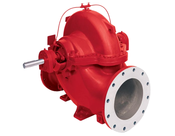
When the pump is running at “churn” (i.e. no flow), churning friction builds up excessive heat in the casing. To prevent overheating and impeller damage, this pressure relief valve is required by code to discharge a continuous cooling stream of fresh water. It should be adjusted to flow at least 3 GPM (or enough to keep the casing cool to the touch). When the pump is stopped, it should be completely closed with zero discharge.
Adjust the packing gland nuts equally for 40 to 60 drops per minute while the pump is running. This controlled leakage is essential to lubricate and cool the shaft and packing rings. If adjustment is needed, adjust the gland nuts one-quarter turn at a time, maintaining equal tightness on both studs so the gland does not cock. Wait at least 10 minutes after each adjustment for the leakage rate to stabilize.
Re-greasable bearing housings feature standard zerk fittings. Lubricate annually with the manufacturer-specified grease grade, maintaining grease volume at 1/3 to 1/2 of bearing cavity capacity. Avoid over-greasing, which causes churning, high operating temperatures, and seal blowouts. Immediately after re-lubrication, bearing temperature may rise temporarily; this stabilizes within 4 to 8 hours.
Verify angular and parallel shaft alignment between the pump and driver every 6 months to prevent premature bearing, seal, or coupling sleeve failure. Inspect the flexible elastomeric insert for wear, cracking, or play. Always verify that all coupling guard panels and mounting bolts are tight and secure before operating the pump.
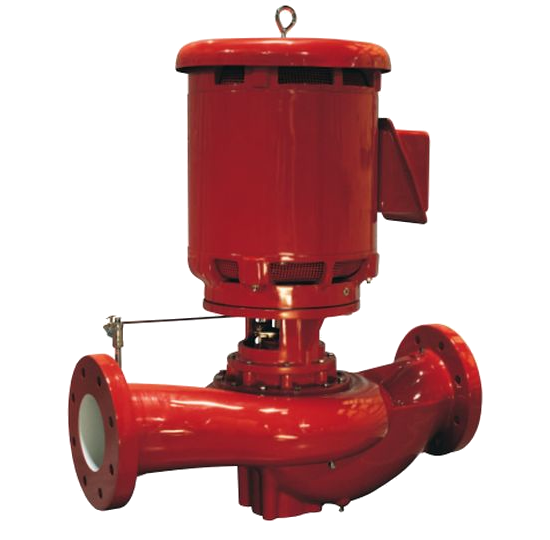
When the pump is running at “churn” (i.e. no flow), churning friction builds up excessive heat in the casing. To prevent overheating and impeller damage, this pressure relief valve is required by code to discharge a continuous cooling stream of fresh water. It should be adjusted to flow at least 3 GPM (or enough to keep the casing cool to the touch). When the pump is stopped, it should be completely closed with zero discharge.
Adjust the packing gland nuts equally for 40 to 60 drops per minute while the pump is running. This controlled leakage is essential to lubricate and cool the shaft and packing rings. If adjustment is needed, adjust the gland nuts one-quarter turn at a time, maintaining equal tightness on both studs so the gland does not cock. Wait at least 10 minutes after each adjustment for the leakage rate to stabilize.
Adjust the packing gland nuts equally for 40 to 60 drops per minute through the stuffing box for shaft lubrication. If the leakage rate is other than this, adjust the gland bolts one-quarter turn at a time (both bolts equally to prevent cocking). Allow approximately 10 minutes for the leakage rate to stabilize before making additional adjustments.
ELECTRIC MOTOR MAINTENANCE
Note: Motor manufacturers typically do not provide "fire pump specific" O&M manuals. When searching for your manual, ensure you select the one specific to the type of motor used (e.g., vertical vs. horizontal).
No components match the selected filters. Try selecting "ALL" in the customization panel.
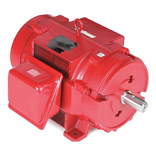
During the monthly operational test run, observe the electric motor for abnormal vibration, excessive heat buildup, or unusual electrical hum. Motor surface temperatures will feel warm during operation, but excessive heat indicates bearing wear, single-phasing, or restricted cooling air. An annual winding insulation resistance test (Megger test per IEEE 43) is recommended to verify coil integrity.
Re-greasable electric motor bearings require periodic lubrication per the motor nameplate (typically every 1 to 3 years or annually for fire pump duty). When greasing:
- Clean the grease zerk and remove the lower drain plug (if equipped) to allow old grease to purge.
- Add the manufacturer-specified grease quantity slowly while the motor is warm.
- Allow the motor to run for 15–30 minutes with the drain plug out to expel excess grease before reinstalling the plug.
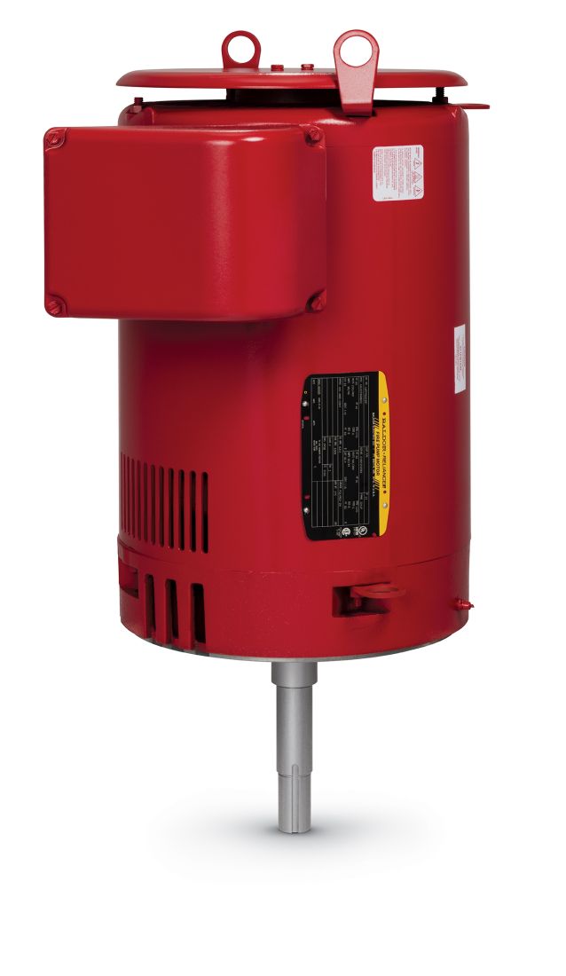
During the monthly operational test run, observe the vertical inline electric motor for abnormal vibration, excessive heat buildup, or unusual electrical hum. Motor surface temperatures will feel warm during operation, but excessive heat indicates bearing wear, single-phasing, or restricted cooling air. An annual winding insulation resistance test (Megger test per IEEE 43) is recommended to verify coil integrity.
Re-greasable vertical inline motor bearings require periodic lubrication per the motor nameplate (typically every 1 to 3 years or annually for fire pump duty). When greasing:
- Clean the grease zerk and remove the lower drain plug (if equipped) to allow old grease to purge.
- Add the manufacturer-specified grease quantity slowly while the motor is warm.
- Allow the motor to run for 15–30 minutes with the drain plug out to expel excess grease before reinstalling the plug.
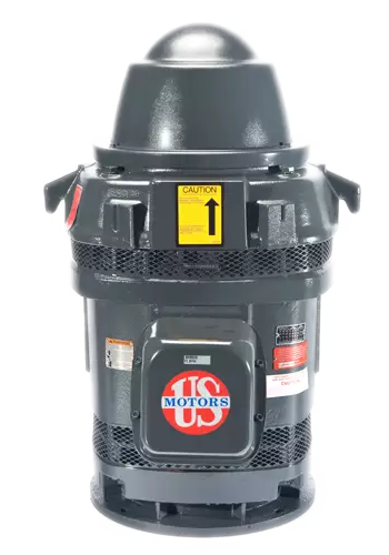
Electric Motors - VT
US MOTORS (High Thrust) - Manual US MOTORS (Normal Thrust) - Manual AURORA - View ManualsCheck the thrust bearing oil sight glass level weekly. The oil must be inspected monthly for evidence of moisture, milkiness, or oxidation. The oil must be drained and replaced whenever contamination is noted or every 12 months, whichever occurs first. Do not overfill!
Monitor the vertical solid shaft / hollow shaft motor for excessive vibration, bearing noise, or overheating during operation. Follow the motor nameplate for specific upper and lower bearing lubrication requirements.
Keep the exterior of the motor, top drip canopy, and ventilation louvers free from dirt, oil, grease, and dust. Blocked ventilation screens lead to rapid motor overheating and insulation failure. Clean ventilation screens periodically using suction/vacuum rather than compressed air to avoid blowing debris into the windings.
DIESEL ENGINE MAINTENANCE
No components match the selected filters. Try selecting "ALL" in the customization panel.
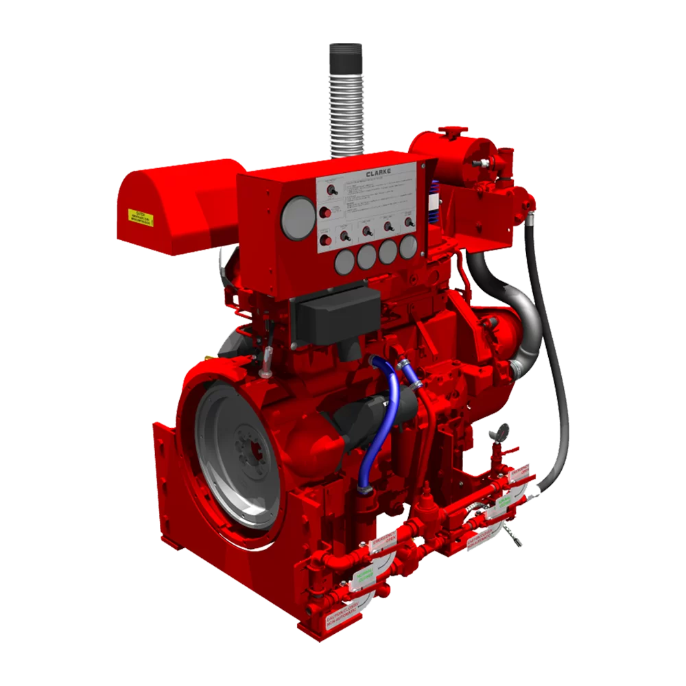
Check the oil level using the dipstick (must be between the ADD and FULL marks). During the annual service (or every 50 operating hours), operate the engine until warm, drain the crankcase oil, replace the oil filter cartridge, and refill with approved 15W-40 CK-4 diesel oil.
Weekly: Drain any water and sediment from the primary fuel filter water
separator bowl. Maintain the fuel storage tank at least 67% (two-thirds) full to minimize
condensation.
Annually: Replace both primary and secondary fuel filter elements, bleed the fuel
system of air, and perform an annual fuel degradation test per ASTM D975.
Weekly: Verify jacket water heater operation (engine block should feel warm,
100°F–120°F) and check coolant expansion reservoir level and hoses for leaks or bulges.
Annually:
Drain, flush, and replace the engine coolant (pre-mixed 50/50 water and anti-freeze with SCA additives) to ensure
heater elements do not burn out and internal cavitation is prevented.
Weekly: While the engine is running, verify adequate cooling water
discharges from the heat exchanger.
6-Months: Clean the Y-strainer screens in both the primary
automatic solenoid line and the manual bypass line.
Annually: Inspect the heat exchanger
sacrificial zinc anode electrode and replace if less than 1 inch long.
Weekly: Check battery electrolyte levels and verify battery charger float
voltage and charging alternator output.
6-Months: Clean and tighten battery posts and cable
connections, coating with terminal grease.
2-Years: Replace all starting batteries entirely to
ensure reliable emergency starting power.
Weekly: Inspect the air cleaner for extreme dirt or rips, and check exhaust
piping and flexible bellows for leaks or excessive smoke.
Annually: Clean reusable air filter
elements using the approved washing/re-oiling procedure, or replace dry cartridge elements.